Setup for CCTV astrophotography from 2006 until 2009
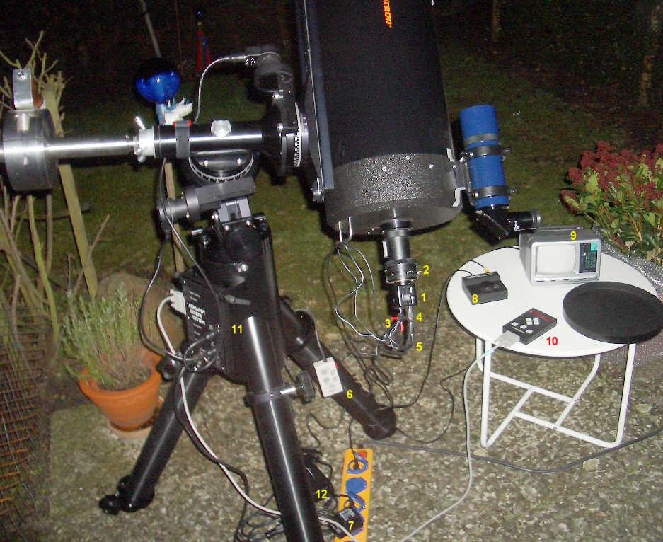
| CCTV camera attached to the telescope The image shows the telescope ready for taking photos of the night sky with a CCTV camera. The numbers in the image refer to the individual components. The tripod is aligned relative to the concrete tiles. The two legs pointing to the lawn are aligned with the edge of a tile. The tile edges run exactly in east-west direction. The mount head is aligned horizontally using the two built-in bubble levels. Azimuth and altitude of the polar axis were aligned using a special function of the Gemini software and are never changed (The Gemini software controls the GoTo version of the Losmandy mounts.). This alignment method is sufficiently accurate even for taking photos with the Watec camera with focus length of more than 2.5 meters. The stability of the Losmandy G11 mount and its tripod is legendary. They carry my telescope with ease. On the first view the cables hang down chaotically and entangling with mount or tripod seems to be very likely. But that is not the case. The cables are long enough and the telescope handle keeps them away from the mount. Only the cable to the declination motor had to be fixed by a velcro strap to the declination axis. A TV set with video input is used as a monitor for focussing and centering of objects. The TV set can be operated with eight 1.5V batteries, a 12V battery, a 12V transformer or AC. If the video signal from the camera is connected to the video input of the monitor and at the same time to the frame grabber card in the PC then both appliances have to share the signal and neither gets the full signal strength. Therefore the switch box 8 switches the video signal from the camera either on the monitor or the frame grabber card. The switch box can be operated in two ways. As shown, the videop signal from the camera is switched on the monitor (via the cable with the yellow plugs) or to the frame grabber card in the PC (not shown). Alternatively a second CCTV camera can be used with a finder scope. In this case the two video signals are switched alternatively on the monitor. The video signal of the camera at the main optics is connected via a Y-plug to the switch box. The video cable to the frame grabber card is plugged into the third connector of the Y-plug. During focussing and centering a weaker video signal is supplied to the monitor. But during exposure the video signal of the finder camera is switched to the monitor and the frame grabber card gets the full signal strength of the camera at the main optics. | |